Designing software architecture with Domain-Driven Design

By Kevin Campusano
May 5, 2026

Photo by Juan Pablo Ventoso, 2023.
This is part 3 of a series of blog posts on Domain-Driven Design:
Domain-Driven Design is an approach to software development that focuses on, as Eric Evans puts it, “tackling the complexity in the heart of software”. And what is in the heart of software? The business domain in which it operates. Or more specifically: a model of it, made of code. That is, the code that implements the business logic that comes into play when solving problems within the realm of a particular business activity.
DDD is not just about writing code though. It’s a whole methodology that touches on business needs, requirements gathering, organizational dynamics, high level architectural design, and lower level patterns for implementing software intensive systems.
As a result, DDD offers a treasure trove of concepts, patterns and tools that can be applied to any software project, regardless of the size and complexity.
In this series of blog posts we’re going to explore many aspects of DDD. We will be following the structure laid out by Vlad Khononov’s excellent book on the topic “Learning Domain-Driven Design: Aligning Software Architecture and Business Strategy”. So you can think of this series as a summary of that book. An abridged version that can serve as a review for anybody who has read it; but also as an entry point for people who are new to DDD.
Table of contents
- Designing software architecture with Domain-Driven Design
Section 8: Architectural patterns
Now that we’ve seen various patterns for implementing business logic, i.e. “the heart of software”. We turn our attention to architecture.
Indeed, the business logic is the raison d’être for a software application. But applications have other responsibilities that are also important. Like interacting with users, receiving requests and returning results, storing data, interfacing with external services. In order to balance all these concerns and make sure the code base does not devolve into an unmaintainable big ball of mud, we need to be intentional in how we organize it. We need to design its architecture.
That is, the rules and principles that we follow to organize the various aspects of the code base and create clear boundaries between them. In essence, software architecture is about defining a system’s big logical components, their dependencies and interactions.
In this section we will see three common architectural patterns: layered architecture, ports and adapters, and command query responsibility segregation.
Layered architecture
The layered architecture is one of the most common architectural patterns out there. It has been present, in one form or another, for a long time. The main idea of the pattern is to separate applications into three layers: the presentation layer, the business logic layer, and the data access layer.
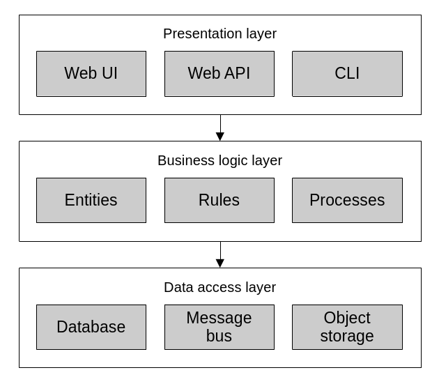
Layered architecture.
The presentation layer (or user interface layer) is meant to implement the mechanisms through which consumers interact with the application. This means the app’s graphical user interface (GUI), command line interface (CLI) or application programming interface (API).
The business logic layer (or domain layer) implements the business rules, validation and invariants. This is where we’d implement the patterns that we’ve seen so far like transaction script, active record, or a domain model.
Sometimes, an additional “service layer” or “application layer” emerges between the presentation and business logic layers. When the domain logic needs some level of orchestration, such as it is the case with active records and domain models, it is often useful to further separate the presentation and business logic layers by exposing a sort of “public interface” to the domain. That is, a series of procedures (i.e. transaction scripts) that serve as a facade that maps presentation layer actions (e.g. user interactions) to business domain transactions.
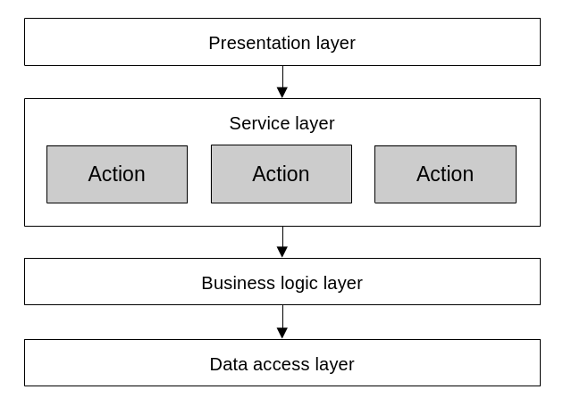
The service layer sits between the presentation and business logic layers. It implements a series of actions which map closely to the operations exposed to users by the presentation layer.
Here’s an example of refactoring a “fat” controller by introducing a service layer:
// This is an MVC controller that implements a REST API endpoint for adding
// items to a shopping cart. It lives in the application's presentation layer
// and leverages business logic layer components to run its logic.

namespace MvcEcommerce.WebApi.Controllers;

[Route("api/[controller]")]
[ApiController]
public class QuoteItemsController : ControllerBase
{
    // ...

    // This action takes care of processing user input, fetching HTTP context
    // values like cookies, responding with proper HTTP status codes and
    // orchestrating the business logic.
    [HttpPost]
    public async Task<ActionResult> Post([FromBody] QuoteItemPost payload)
    {
        var quoteId = _quoteCookieManager.GetQuoteIdFromCookie(Request);
        var quote = await _quoteRepository.FindOpenByIdAsync(quoteId);
        if (quote == null) return NotFound("Quote not found");

        var product = await _productRepository.FindByIdAsync(payload.ProductId);
        if (product == null) return NotFound("Product not found");

        var matchingQuoteItem = quote.GetItemBy(productId: payload.ProductId);
        if (matchingQuoteItem != null) return BadRequest("Item already exists");

        var quoteItem = new QuoteItem()
        {
            Product = product,
            Quantity = payload.Quantity,
        };
        quote.Items.Add(quoteItem);

        await _quoteRepository.UpdateAsync(quote);

        return Ok(quoteItem);
    }
}
This controller does too much. We can move a lot of its logic into a service layer component:
namespace MvcEcommerce.WebApi.Controllers;

[Route("api/[controller]")]
[ApiController]
public class QuoteItemsController : ControllerBase
{
    // ...

    // After refactoring, this action is now much simpler and only concerned
    // with presentation layer issues. That is, handling user input and the HTTP
    // specific aspects of request processing. It relies on the service layer to
    // orchestrate the business logic.
    [HttpPost]
    public async Task<ActionResult> Post([FromBody] QuoteItemPost quoteItem)
    {
        try
        {
            var quoteId = _quoteCookieManager.GetQuoteIdFromCookie(Request);

            var result = await _quoteItemCreator.Run(new() {
                QuoteId = quoteId.Value,
                ProductId = quoteItem.ProductId,
                Quantity = quoteItem.Quantity
            });

            return Ok(result);
        }
        catch (EntityNotFoundException ex)
        {
            return NotFound(new ErrorMessage(ex));
        }
        catch (DomainException ex)
        {
            return BadRequest(new ErrorMessage(ex));
        }
    }
}
// This service object implements all the domain logic orchestration that
// used to live in the controller. Notice how this code is not concerned with
// presentation layer responsibilities like handling HTTP specific logic, for
// example.
namespace MvcEcommerce.ServiceLayer.Services;
public class QuoteItemCreator
{
// ...
public async Task<QuoteItem> Run(InputPayload payload)
{
var product =
await _productRepository.FindByIdAsync(payload.ProductId) ??
throw new EntityNotFoundException("Product not found");
var quote =
await _quoteRepository.FindOpenByIdAsync(payload.QuoteId) ??
throw new EntityNotFoundException("Quote not found");
var matchingQuoteItem = quote.GetItemBy(productId: payload.ProductId);
if (matchingQuoteItem != null)
throw new DomainException("Item already exists");
var quoteItem = new QuoteItem()
{
Product = product,
Quantity = payload.Quantity,
};
quote.Items.Add(quoteItem);
await _quoteRepository.UpdateAsync(quote);
return quoteItem;
}
}Finally, the data access layer is meant to provide the means of interacting with persistent storage like databases, search indexes, file systems, etc. In modern systems, this layer has evolved into more of a “infrastructure” layer, and taken on the responsibility of interacting with external APIs and other kinds of web services. So, not strictly limited to pure “data storage”.
The communication between these layers is one-way, from top to bottom. Meaning that the presentation layer holds a reference to, depends on, and calls to the business logic layer. Same with the business logic layer to the data access layer.
This communication pattern is excellent for active record and transaction script based systems. For domain models, it begins to fall a bit short. This is because the business logic depending on the data access logic contradicts one of the core principles of domain models: the fact that they are supposed to be plain old objects, with no dependencies on frameworks or infrastructure.
Ports and adapters
The ports and adapters architecture leverages the dependency inversion principle to address the shortcomings of the traditional layered architecture and make it ideal for implementing domain models. Its main advantage is that it decouples the business logic layer from the infrastructure.
The dependency inversion principle dictates that, instead of higher level components directly depending on and referencing lower level ones; it is the lower level components that should depend on the higher level ones. This is done by the higher level components defining contracts for the lower level components to implement, and through those, be integrated into the higher level components’ workflows. The higher level components only ever interact with the lower level ones through the contracts that they themselves define.
Case in point: instead of the business logic depending on data access logic, like in the layered architecture; the business logic layer takes center stage and defines the contracts that the data access layer (and really, all infrastructure) must abide to in order to be usable to the business logic.
And that’s precisely where the ports and adapters name comes from. The business logic defines contracts/interfaces, AKA “ports”; and the infrastructure provides concrete implementations for these interfaces which can talk to external components: the “adapters”. Then, application bootstrapping logic, or dependency injection, takes care of supplying the concrete objects (or adapters) to the abstract interfaces (or ports) that the business logic specifies. This is exactly what a domain model calls for.
Here’s an example of a minimal, thin vertical slice of an application designed using the ports and adapters pattern:
The business logic implements some procedure which necessitates interacting with the database, an email delivery service, and a payment processor:
namespace Ecommerce.BusinessLogicLayer.Services;

public class OrderCreator
{
    // This service does not directly depend on concrete classes. Instead, it
    // references abstract interfaces. The concrete implementations are given
    // via dependency injection through the constructor.
    private readonly IOrderRepository _orderRepository;
    private readonly IOrderConfirmationMailer _orderConfirmationMailer;
    private readonly IPaymentGateway _paymentGateway;

    public OrderCreator(
        IOrderRepository orderRepository,
        IOrderConfirmationMailer orderConfirmationMailer,
        IPaymentGateway paymentGateway
    ) {
        _orderRepository = orderRepository;
        _orderConfirmationMailer = orderConfirmationMailer;
        _paymentGateway = paymentGateway;
    }

    public async Task<Order> Run(InputPayload payload)
    {
        // ...

        var order = new Order(payload);

        var result = _paymentGateway.SubmitPayment(order);
        if (!result.IsSuccess)
            throw new DomainException("Error processing payment");

        await _orderRepository.Save(order);

        await _orderConfirmationMailer.Send(order);

        return order;
    }
}
The business logic layer also defines its ports. That is, interfaces that the infrastructure layer will have to implement:
namespace Ecommerce.BusinessLogicLayer.Interfaces;

public interface IPaymentGateway
{
    PaymentTransactionResult SubmitPayment(Order order);
}

public interface IOrderRepository
{
    Task<Order> Save(Order Order);
}

public interface IOrderConfirmationMailer
{
    Task Send(Order order);
}
The infrastructure layer provides implementations for these interfaces:
namespace Ecommerce.InfrastructureLayer.Payments;

public class AuthorizeNetPaymentGateway : IPaymentGateway
{
    public AuthorizeNetPaymentGateway(/* ... */) { /* ... */ }

    public PaymentTransactionResult SubmitPayment(Order order) { /* ... */ }
}
namespace Ecommerce.InfrastructureLayer.Repositories;
public class OrderRepository : IOrderRepository
{
public OrderRepository(/* ... */) { /* ... */ }
public Task<Order> Save(Order Order) { /* ... */ }
}namespace Ecommerce.InfrastructureLayer.Mailers;
public class OrderConfirmationAwsSesMailer : IOrderConfirmationMailer
{
public OrderConfirmationAwsSesMailer(/* ... */) { /* ... */ }
public Task Send(Order order) { /* ... */ }
}Like mentioned before, everything can be wired together via dependency injection or some other form of bootstrapping. Most frameworks have their own way of resolving dependencies and instantiating service objects like these; in order to execute them as a result of requests from consumers (e.g. a CLI command, a web request, the click of a button). In essence, it’s something like this:
var repository = new OrderRepository(dbContext);
var mailer = new OrderConfirmationAwsSesMailer(mailerConfig);
var paymentGateway = new AuthorizeNetPaymentGateway(paymentConfig);

var orderCreator = new OrderCreator(repository, mailer, paymentGateway);

orderCreator.Run(payload);
So, the ports and adapters architectural pattern has a business logic layer which has no dependencies on any other components outside of itself. It defines a set of interfaces for all external components that want to interact with it. It also has an infrastructure layer which implements concrete classes for the domain layer’s interfaces. Data access, interaction with external services, user interface, and presentation logic all live here. And finally, it has a service/application layer which, similar to its counterpart from the layered architecture, can emerge between the business logic and infrastructure layers when needed to expose a set of procedures that closely map to user interface actions. It exposes all the business operations that the system supports and orchestrates the business logic to carry them out.
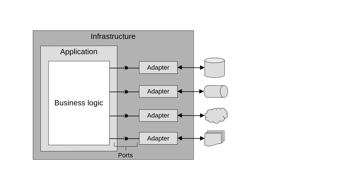
When organizing the code following the the ports and adapters architectural pattern, the business logic layer defines interfaces/ports, which the infrastructure layer implements concrete objects for. These objects take care of interacting with the external world.
Clean architecture, onion architecture and hexagonal architecture are all different names for the same core concepts and principles espoused by ports and adapters; sometimes with slight variations depending on the particular flavor and tech stack.
Command query responsibility segregation
The command query responsibility segregation pattern (CQRS) builds on the principles from ports and adapters and adds support for multiple different representations of the system’s data. That is, having multiple persistence models for the same data set. One of the most common examples is a system that stores and operates on day to day business transactions using an OLTP (online transaction processing) representation, but also needs to provide an OLAP (online analytical processing) data warehouse for high level business analysis. One ground-truth source of data (the OLTP) is used to produce additional representations with a different schema (the OLAP). CQRS enables this.
As such, CQRS is ideal for event sourced domain models, because it allows persisting the many projections of an aggregate’s data into their own databases. (Remember that in the context of event sourcing, a projection is a representation of the state of a business entity which is constructed based on its stored domain events). It allows of course, querying of these projections with much more flexibility than what a pure event store allows on its own.
At the core of CQRS there are two types of models: a command execution model (the C in CQRS) and one or many read, or query, models (the Q in CQRS). In database terms, this is similar to a primary-replica type of situation, where the command execution model represents the primary, and the read models represent the replicas.
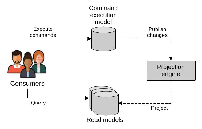
CQRS exposes two types of models, one for executing commands and many others for reading. In the backend, a projection engine keeps the read models up to date with the latest changes from the command execution model.
The command execution model is the system’s source of truth, whose data is strongly consistent. It’s the one used to execute and record business operations, and enforce business rules and invariants. All operations that result in changes to the system state are handled here.
The query, or read, models take care of exposing different projections of the system state. These are read-only models that are meant for presenting the system’s data to its consumers. They are generated based on the main data source, which is the data maintained in the command execution model. In fact, read models should be capable of being easily destroyed and recreated from the main data.
Read models are generated using components that we call projection engines, which can work synchronously or asynchronously when fetching data from the command execution model to generate their projections.
Synchronously, projection engines generate read models using a catch-up subscription design. It works like this:
- The projection engine determines the last query checkpoint. Basically, when was the last time it read the main database.
- The projection engine queries the main database and identifies newly added and updated records since the last query checkpoint.
- The projection engine uses the new data to regenerate or update the read model.
- The projection engine updates the latest query checkpoint, to be used during the next execution of the engine, starting again at step 1.
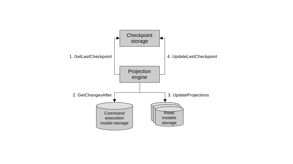
Synchronous projection engine.
This checkpoint can be implemented in various ways. The main idea is to offer a mechanism for the projection engine to be able to tell which records are new or have changed since its last run. One way to do it is using something akin to SQL Server’s rowversion feature. This is a database-wide, auto-incrementing numeric value that increases after every INSERT and UPDATE operation. The newly incremented value is assigned to the rows that were added or updated. With this, the projection engine can easily query all records whose rowversion is greater than the last checkpoint. Similar functionality can be implemented using database triggers too. Or database tables can also include timestamp fields that indicate when records were last touched.
Asynchronous projection engines on the other hand, rely on the command execution model publishing all changes to a message bus. The projection engine can subscribe to these messages and update its read model as they come. This method, while scalable, comes with drawbacks inherent to distributed computing like handling duplicates and out of order messages. It’s also more difficult to destroy and regenerate read models that rely on asynchronous messaging only, since the messages are gone after they are processed. Often the better solution is to use a synchronous design and then, only if needed, augment it with the asynchrony.
Naturally, CQRS is ideal when the system needs to support different types of databases. Imagine an online store, for example, which has an inventory management component that works directly with the command execution model backed by a relational database. But for displaying the product catalog to users, it uses a read model backed by a search index, optimized for full text search. And for event sourced domain models, CQRS is practically mandatory.
Scope
The patterns that we’ve seen in this section are not exclusively meant as system-wide nor even bounded-context-wide organizational principles. Arbitrarily enforcing a single pattern everywhere often leads to accidental complexity. Instead we should follow DDD’s core principles and deploy these strategies according to what the business domain necessitates. Indeed, within a bounded context, especially one that deals with many subdomains, there should be logical separation between these subdomains. Each resulting module could use a different architectural pattern. In other words, these patterns divide the code base into horizontal slices; and the subdomains can be used to define the vertical slices. This way, a monolithic bounded context can be modularized. This leaves the code base in a good position for future refactoring and further physical separation into distinct bounded contexts in the future (i.e. into separate applications, services and/or processes).
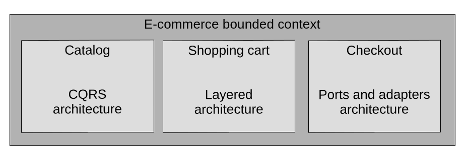
When needed, different architectural patterns can be deployed to different subdomains within the same bounded context.
Section 9: Communication patterns
In the last few sections we’ve discussed how to implement business logic and how to leverage architectural patterns to organize the code within a bounded context. In this section, we will take a higher level view and go beyond the scope of a single bounded context. We will learn about patterns of communication across bounded contexts. In other words, how to integrate them.
Model translation
Back when we talked about integrating bounded contexts, we discussed how they can use different communication strategies depending on the disposition of the teams that own them. When the teams have strong communication, cooperation patterns like partnership and shared kernel can be used for integration. Here, bounded contexts can communicate without friction. The protocols for doing so are defined by the teams in an ad-hoc manner and development moves forward without too many issues.
However, when the teams are not closely aligned, and cooperation patterns are impossible, a customer-supplier relationship emerges. This can be addressed by implementing an anticorruption layer in the downstream consumer, to adapt the upstream supplier’s model to the consumer’s needs. Another option is for the upstream supplier to implement an open-host service and expose an integration-specific published language, which isolates consumers from the details of its internal model. Both approaches are meant to protect a bounded context’s model from the influence of external models.
In these non-cooperation cases, we have to be more intentional in how we design the communication between bounded contexts, and the need for a translation of their models/languages arises. This logic that translates the models can either be stateless or stateful.
Stateless model translation
Stateless model translation can happen on the fly via the proxy design pattern. The idea is to put an intermediary component in place, which receives messages in one language, translates them, and forwards them to their destination.
If the proxy is implemented by the consumer or downstream component, functioning as an anticorruption layer, then it intercepts outgoing requests and translates them to a language that the upstream supplier can understand. It does the same with the incoming responses from upstream: it translates them to a language that the consumer can understand.
If the proxy is implemented by the supplier or upstream component, it functions as an open-host service. It takes the incoming requests that arrive using the published language and translates them to the supplier’s internal one. Then, outgoing responses get translated to the published language.
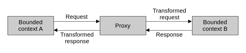
In essence, a proxy is nothing more than a component that sits between two other components and translates the messages passing between them.
These proxies can be synchronous or asynchronous.
Synchronous translation is straightforward. Messages are translated just as they are being received or sent, depending on whether the translation happens upstream or downstream. Normally, the translation logic is implemented directly in the bounded context that needs it.
In some cases though, it makes sense to separate it into its own independent component, implementing an API gateway pattern. Sometimes, off the shelf software or cloud services like KrakenD or AWS API Gateway can be used to implement them.
Having a separate API gateway has some advantages, other than the obvious decoupling of model translation logic from actual business logic. It can make it easier to expose multiple versions of the API. That is, of the published language. It can also be consumed by multiple downstream components, making it essentially an integration-specific bounded context. We call these, interchange contexts.
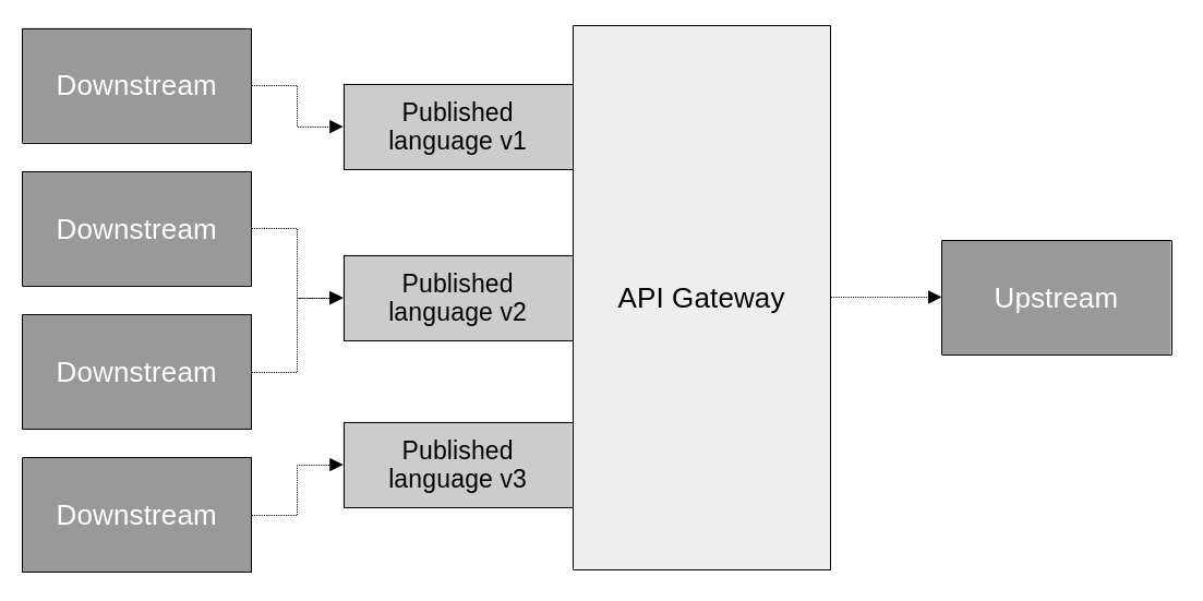
When extracted into its own component, a proxy becomes an API gateway. This is useful for further separation of concerns, offering multiple versions of the API’s published language, and serving multiple consumers.
Asynchronous translation on the other hand, is not direct. It relies on an event driven design to implement a message proxy; which subscribes to events published by one bounded context, translates them, and forwards them to their destination.
The proxy can also apply filtering to the messages, deciding which ones to forward and which ones to ignore. This is useful, for example, to keep the published language free of domain events that are meant to be internal to the bounded context that produces them.
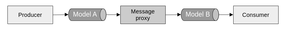
An asynchronous proxy listens to events in one language and translates them to another language.
Stateful model translation
Stateful model translation comes into play when more complex translation logic that requires persistent storage is needed. This is useful for two common scenarios: when the requests need to be aggregated, and when data from multiple sources needs to be unified. In both cases the component doing the translation needs to keep track of the incoming requests and messages. It stores them in a database in order to reconstruct them eventually.
Data aggregation may be needed for performance reasons when, for example, multiple requests need to be collected together and dispatched as one batch. Another case is when multiple disparate messages need to be combined into one single bigger message that conveys more complete information. This can work both synchronously and asynchronously. That is, the messages can be direct requests or published events.
An API gateway on its own is not appropriate for this type of model translation, as it doesn’t provide persistent storage or more complex processing logic beyond mapping and rerouting. Instead, it can be implemented from scratch as a bespoke solution, or leveraging off the shelf stream processing platforms like Apache Kafka or AWS Kinesis.
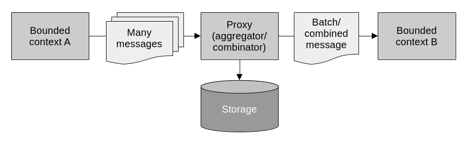
A proxy can aggregate and/or combine multiple separate messages into a single one for performance and consolidation purposes.
The unification of multiple data sources is also a common use case for stateful model translation. This is necessary for example when a component needs to process data from many different upstream suppliers and apply complex business logic to it. This is commonly seen in the backend for frontend pattern. In this pattern, an API is defined to meet all of a frontend’s needs, while serving as a facade for a number of backend services. This allows the frontend to call a single backend to interact with all the various services it may need.
Integrating aggregates
Before, we talked about the rules that we follow to limit the scope of aggregates and ensure they encapsulate a coherent set of business logic. We strive to keep them focused, with tight boundaries. They represent strong data consistency and transactional boundaries. That is, they should only contain strongly consistent data and the system’s transactions should be limited to a single aggregate instance. It is also true however, that there are business processes that involve multiple aggregates. The following patterns allow us to implement such business processes without breaking the aggregates’ isolation rules.
Outbox
As we know, along with commands, domain events are part of an aggregate’s public interface. By publishing domain events to a message bus, aggregates communicate with the outside world. Or more specifically, to their subscribers, who listen to these events in order to trigger their own logic. The outbox pattern allows aggregates to reliably publish domain events.
The outbox pattern works by storing domain events in the same database as the aggregate’s data. Leveraging database transactions to ensure both the state changes and the events are saved atomically. The process is this:
- Aggregate state changes and new events are committed in the same database transaction.
- The message relay picks up the new events from the database.
- The message relay publishes the new events to the message bus.
- After successful publishing, the message relay marks the event as such, or deletes it.
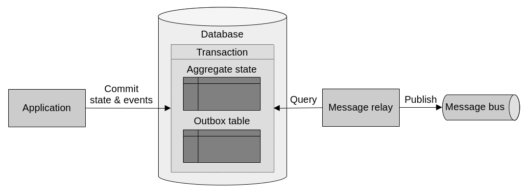
The outbox pattern is about storing an aggregate’s domain events in a database, making sure to commit them in the same transaction as state changes.
Saga
A saga leverages the reliable publishing of domain events afforded to us by the outbox pattern to implement business processes that span multiple aggregates. They do this by listening to events and responding to them by issuing commands to relevant components. A saga represents a long-running business process. One that spans multiple transactions.
Sagas can vary in complexity. Sometimes it is enough to respond to events by directly issuing commands from the saga itself.
public class OrderProcessingSaga
{
    private readonly IOrderRepository _orderRepository;
    private readonly IPaymentService _paymentService;
    private readonly IInventoryService _inventoryService;
    private readonly IShippingService _shippingService;

    //...

    // These event handler methods all follow a similar pattern:
    // Receive the event, then call the corresponding command.
    public void Process(OrderCaptured @event)
    {
        var order = _orderRepository.Fetch(@event.OrderId);

        _paymentService.ProcessPayment(order);
    }

    public void Process(PaymentAccepted @event)
    {
        var order = _orderRepository.Fetch(@event.OrderId);

        _inventoryService.PreparePackage(order);

        order.UpdateStatus(@event.NewOrderStatus);
        _orderRepository.Save(order);
    }

    public void Process(InventoryCleared @event)
    {
        var order = _orderRepository.Fetch(@event.OrderId);

        _shippingService.ScheduleDelivery(order);

        order.UpdateStatus(@event.NewOrderStatus);
        _orderRepository.Save(order);
    }

    public void Process(ShipmentDispatched @event)
    {
        var order = _orderRepository.Fetch(@event.OrderId);

        order.UpdateStatus(@event.NewOrderStatus);
        _orderRepository.Save(order);
    }
}
Other times, a saga needs to keep its own state. For example, when the saga needs to track received events; to react to certain failure conditions; issue retries, etc. In these cases, the saga can be implemented as an event sourced aggregate, keep a record of all received events, and publish events of its own that contain the commands that it wants to execute. Then, a separate message relay component should be listening to the saga’s events and run the commands contained within.
public class OrderProcessingSaga
{
    // Like any other event sourced aggregate, this saga stores its list of
    // events.
    private readonly IList<DomainEvent> _events = [];

    // ...

    // These event handlers all also follow a similar pattern. Instead of
    // directly calling the commands though, they register an event with the
    // necessary information for the message relay to call the commands.
    public void Process(OrderCaptured @event)
    {
        // ...

        _events.Append(@event);
        _events.Append(new CommandIssuedEvent(
            target: Target.PaymentService,
            command: new ProcessPaymentCommand(@event.OrderId)
        ));
    }

    public void Process(PaymentAccepted @event)
    {
        // ...

        _events.Append(@event);
        _events.Append(new CommandIssuedEvent(
            target: Target.InventoryService,
            command: new PreparePackageCommand(@event.OrderId)
        ));
    }

    public void Process(InventoryCleared @event)
    {
        // ...

        _events.Append(@event);
        _events.Append(new CommandIssuedEvent(
            target: Target.ShippingService,
            command: new ScheduleDeliveryCommand(@event.OrderId)
        ));
    }

    public void Process(ShipmentDispatched @event)
    {
        // ...

        _events.Append(@event);
    }
}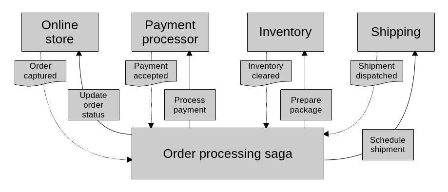
Sagas represent a long running business process. One that spans many transactions. They receive events and invoke commands as a result.
Always remember though, sagas make it possible to implement business processes that span multiple aggregates, but the data across aggregates is only eventually consistent. The core aggregate design rules still apply: only the data within an aggregate is strongly consistent.
Process manager
The process manager pattern is essentially a more complex saga. While sagas mostly deal with linear flows, and direct mapping between events and commands; a process manager implements more complex business logic that keeps track of the sequence of events, has its own state, and determines how to react. It does not only have a simple mapping of events to commands. Instead it has complex logic that decides how to respond to incoming events. It is a central processing unit, listening to events from and issuing commands to multiple sources, and managing an overall business process.
Another difference between them is that sagas are instantiated implicitly, while process managers are instantiated explicitly. Meaning that sagas live and die within the context of the events that they listen to. They “get activated” when an event that they are interested in is published. Process managers on the other hand get activated when the business process they manage gets initiated. They stay alive through the duration of the process’s many steps.
Implementation wise, they are essentially aggregates with a strong focus on responding to events. They have their own persistent state, explicit identity, lifecycle, and related objects; as well as a series of event handlers, just like a saga would have.
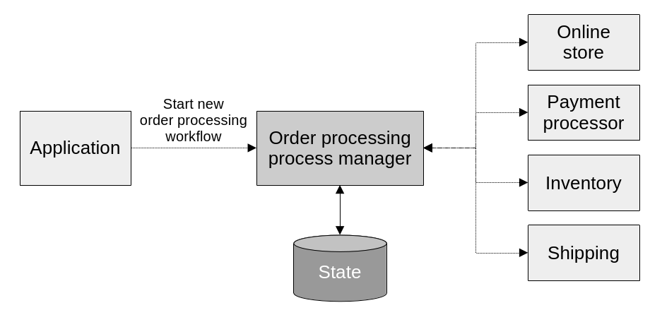
A process manager orchestrates a long running business process with complex logic that involves many components. The application layer instantiates them explicitly, as it would any other aggregate.
public class OrderProcessManager
{
    private readonly IList<DomainEvent> _events = [];

    // Process managers have their own explicit identity. They are very similar
    // to aggregates or entities.
    private OrderId _id;

    // They can include other properties to track state as needed.

    // ...

    // Process managers usually include an initialization procedure that kicks
    // off the process, and provides the necessary parameters.
    public void Initialize(/* ... */)
    {
        // ...

        _events.Append(orderProcessingInitiated);
        _events.Append(new CommandIssuedEvent(
            target: Target.PaymentService,
            command: new ProcessPaymentCommand(@event.OrderId)
        ));
    }

    // The event handlers are very similar to those of the event sourced
    // stateful saga. The difference is that here they run more complex logic to
    // determine how to continue the process. As opposed to the saga's simpler
    // mapping of incoming events to commands.
    public void Process(PaymentAccepted @event)
    {
        // ...

        _events.Append(@event);
        _events.Append(new CommandIssuedEvent(
            target: Target.InventoryService,
            command: new PreparePackageCommand(@event.OrderId)
        ));
    }

    public void Process(InventoryCleared @event)
    {
        // ...

        _events.Append(@event);
        _events.Append(new CommandIssuedEvent(
            target: Target.ShippingService,
            command: new ScheduleDeliveryCommand(@event.OrderId)
        ));
    }

    public void Process(ShipmentDispatched @event)
    {
        // ...

        _events.Append(@event);
    }
}
Architectural patterns to use within bounded contexts
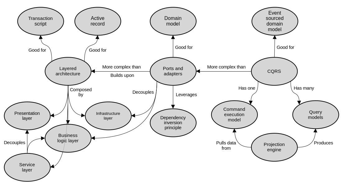
These are the main concepts around the architectural patterns that we’ve discussed.
Patterns for communicating across bounded contexts
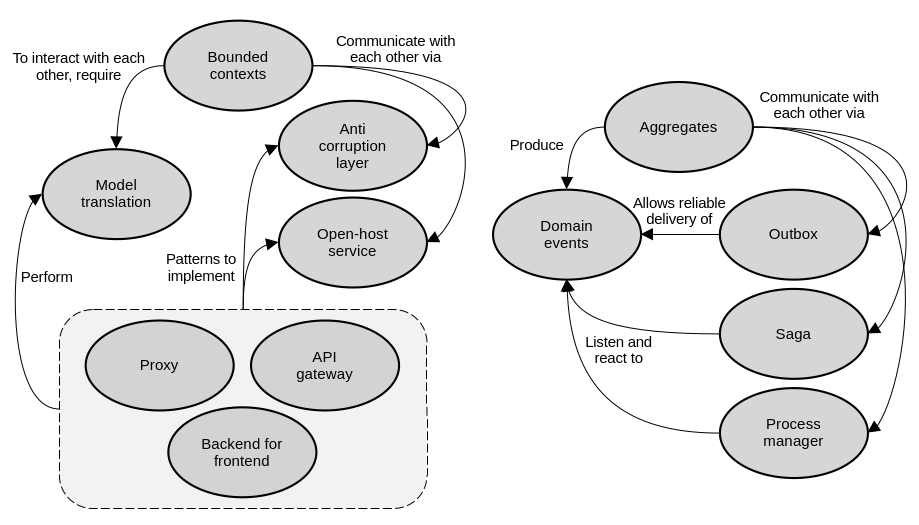
These are the main concepts around the communication patterns that we’ve discussed.
software architecture design books
Comments