Announcing the Cesium KML-CZML Editor

By Dmitry Kiselev
December 21, 2020
End Point’s immersive technology team is happy to present a great new tool for the rapidly growing Cesium community: Cesium KML-CZML Editor. The editor gives users the ability to visually and dynamically edit KML and CZML in its Cesium browser window. Updates made with it can be exported at any time to CZML, the native markup language for Cesium.
The Cesium KML-CZML Editor addresses an important but hitherto unaddressed need of the Cesium community: It provides an intuitive interface for making adjustments to fix the many inconsistencies with how KML created for (and often by) Google Earth appears on 3D maps rendered with Cesium. It is a powerful tool for converting and adapting KML for Google Earth into CZML that displays nicely in Cesium. The editor also works as a visual editor for creating and editing CZML, regardless of whether you’re converting from KML.
The inconsistencies with how Cesium displays KML created for Google Earth are due to occasional differences between how Cesium and Google Earth render KML when various attributes aren’t specifically set within a given instance of code. The situation is similar to how web browsers sometimes interpret given instances of HTML differently. Just as with HTML, KML doesn’t require every attribute to be defined in a given instance of markup code.
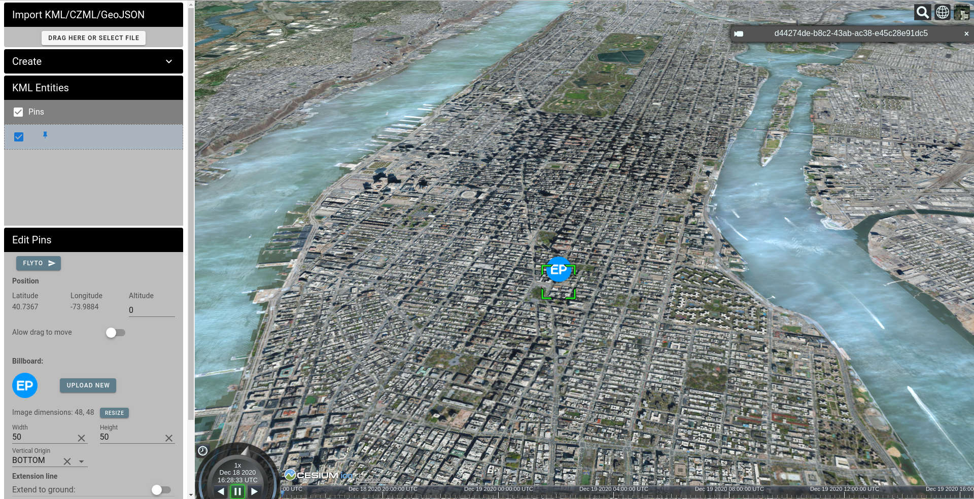
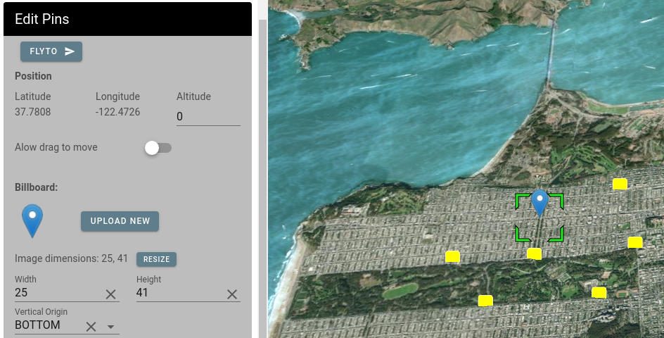
On the left side we have the editor toolbar, and on the right side the Cesium globe showing loaded or created entities the way they would appear in Cesium.
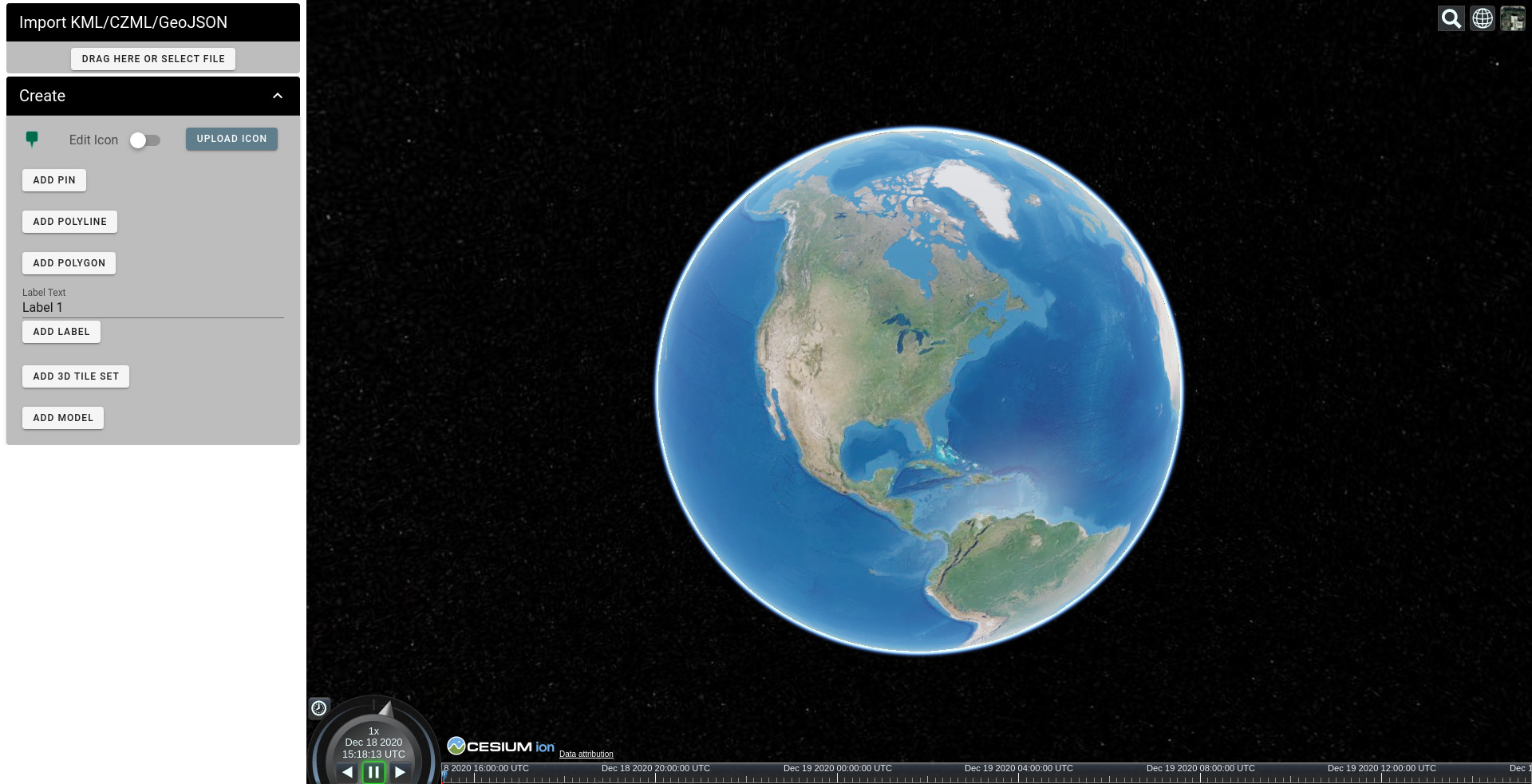
The Editor Toolbar consist of the following areas:
- File Import: you can load KML, KMZ, CZML and GeoJSON formatted data, and you can load multiple files to combine them into one CZML document.
- Creation tools.
- A list of uploaded or created entities (will appear after upload or creation of a new entity).
- The actual editor for entity properties (will appear after entity selection).
Let’s start with a very basic example of highlighting a building by marking it with a pin in Google Earth:
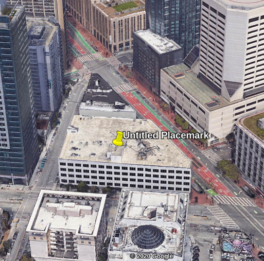
Now let’s move the camera about in different ways, especially noticing how the pin appears when zooming in and out. The pin stays close to the top of the building.
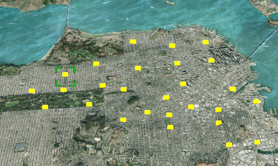
Then let’s open the same KML in Cesium with a 3D building tileset loaded, to compare apples to apples:
It’s easy to see that the green frame which is placed around the geographic position stays around the building, but the icon point of rotation in Cesium doesn’t match the one in Google Earth and the pin falls through the roof and lifts up unfortunately high above the building.
KML doesn’t enforce certain aspects of its representation. If certain attributes are not specified or can’t be implemented exactly, then the KML browsers have the freedom to set different default values for them.
In this example, Cesium and Google Earth display different pixel offsets for the pin icon, because in KML the offset is specified as a ratio of the image, but Cesium specifies the offset in pixels. Cesium converts the pixel offset of the pin from the ratio specified, but with some errors. Cesium reverses the X axis, and in some cases Cesium also calculates the pin icon image size incorrectly. So here it calculates the X offset as -4, which moves the pin icon to the left. To fix that, we can reverse the X axis back to 4 or even move the pin icon 8 pixels further to the right.
 🡆
🡆
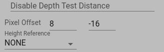
The next issue is how the Z coordinate (altitude) is interpreted. Is it above sea level, above land according to some averaged model of the land, or on the land directly below a point?
Note that 3D tilesets in Cesium are absolutely positioned. This means that if you show 3D buildings and want your pin to stick to a building, it’s better to use absolute elevation. Hence, it makes sense to set Height Reference to NONE, which will force Cesium to use the absolute pin position.
Another option in cases like this is to use relative elevation. This can be helpful if you don’t use 3D tiles, but instead use 3D terrain data, for example, with Cesium World Terrain or Maptiler. It’s especially helpful if you will be switching 3D terrain on and off. In this case, a relatively positioned pin will follow the elevation regardless of whether 3D terrain is turned on or off.
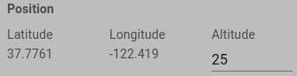
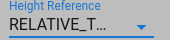
To set it up, adjust Altitude and set Height Reference to RELATIVE_TO_GROUND:
Here are the results for both options:
As you can see, now we have the pin-point of the marker stuck to the desired location.
These are the basics for how to match pins created in Google Earth with their Cesium representations, but in Cesium there are many more options for rendering pins. You can read the relevant Cesium documentation (in Cesium terminology Pins are called Billboards) or interactively explore a live version of this editor to change color, rotation, translucency by distance, and other properties.
Now let’s look at a polygon created in KML for Google Earth:
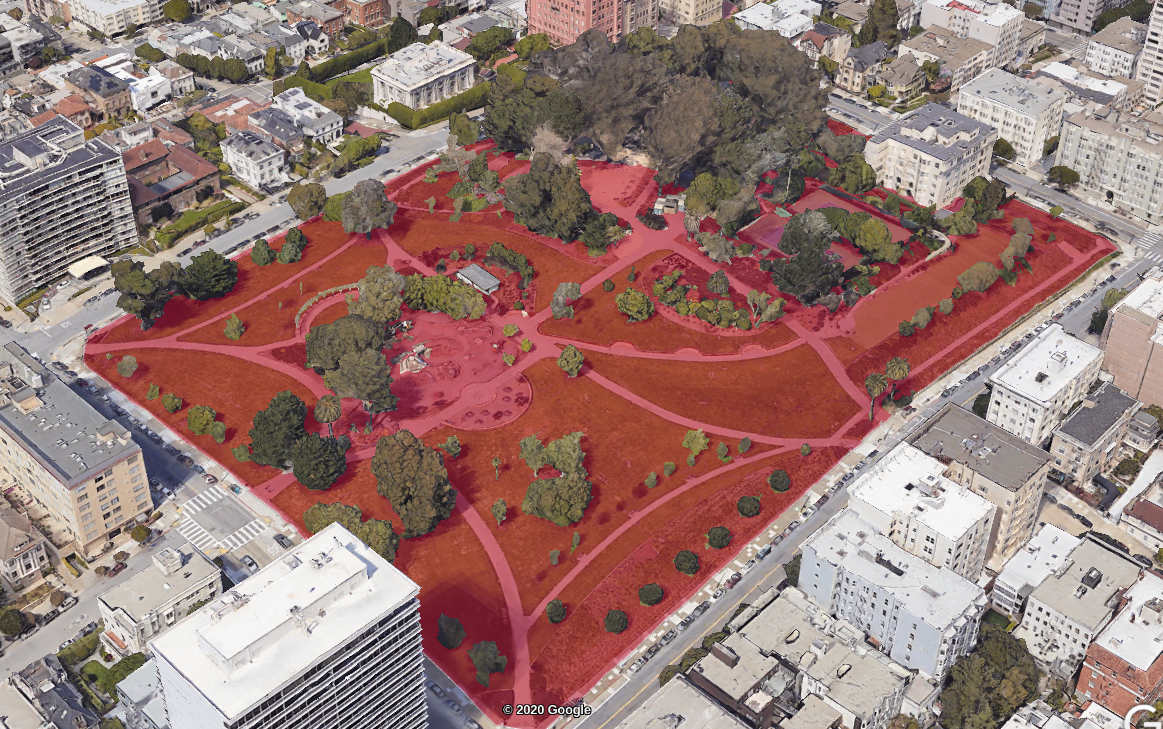
Then let’s open it in Cesium:
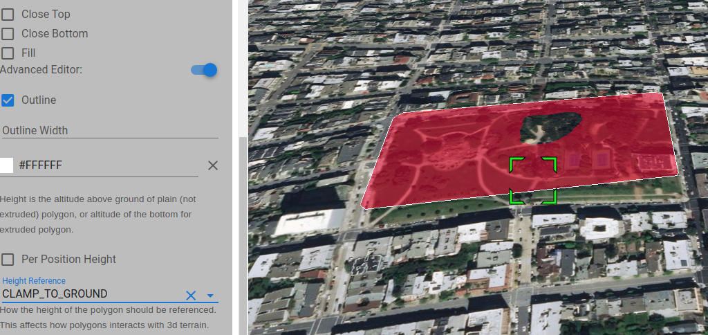
Well, we can select a polygon, but we don’t see it. This happens because the 3D terrain data covers the polygon. Just changing the Height reference helps, but it’s still not what we want:
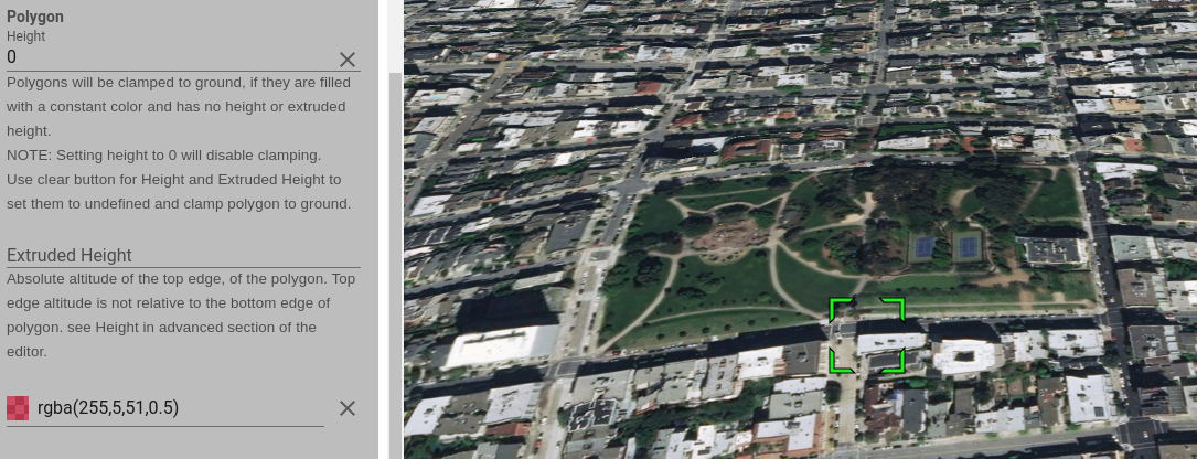
Cesium has some default assumptions about polygons and rectangles and when to clamp them to the ground.
As commented in the Cesium SandCastle Clamp to Terrain demo code:
Corridors, polygons and rectangles will be clamped automatically if they are filled with a constant color and have no height or extruded height.
NOTE: Setting height to 0 will disable clamping.
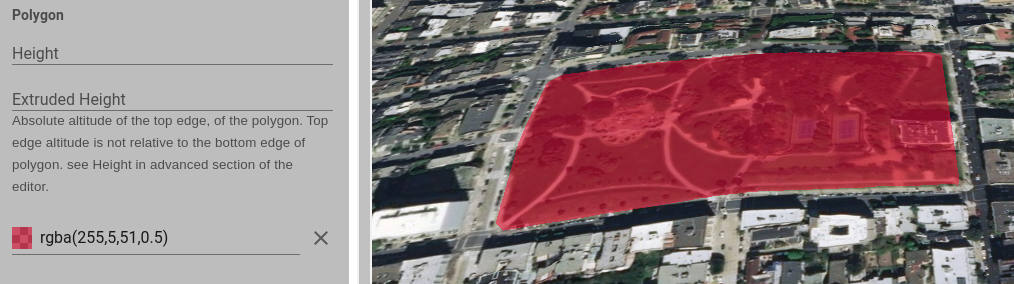
So to get a polygon actually clamped to ground, we have to delete the Height property, not just set it to 0:
Now let’s add a 3D tileset:
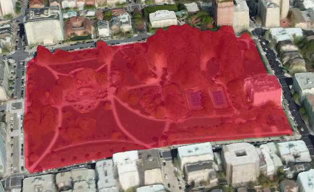
And again, this is probably not exactly what you wanted. By default, Cesium doesn’t know what type of 3D tileset you would prefer, or whether you want the polygons to cover the tiles, or the tiles to cover the polygons. If you have a fairly large polygon covering a whole city, and a fairly low resolution 3D tileset, you probably want to highlight the whole area. But in the example above, we want our polygon to stick to the ground but not the buildings.
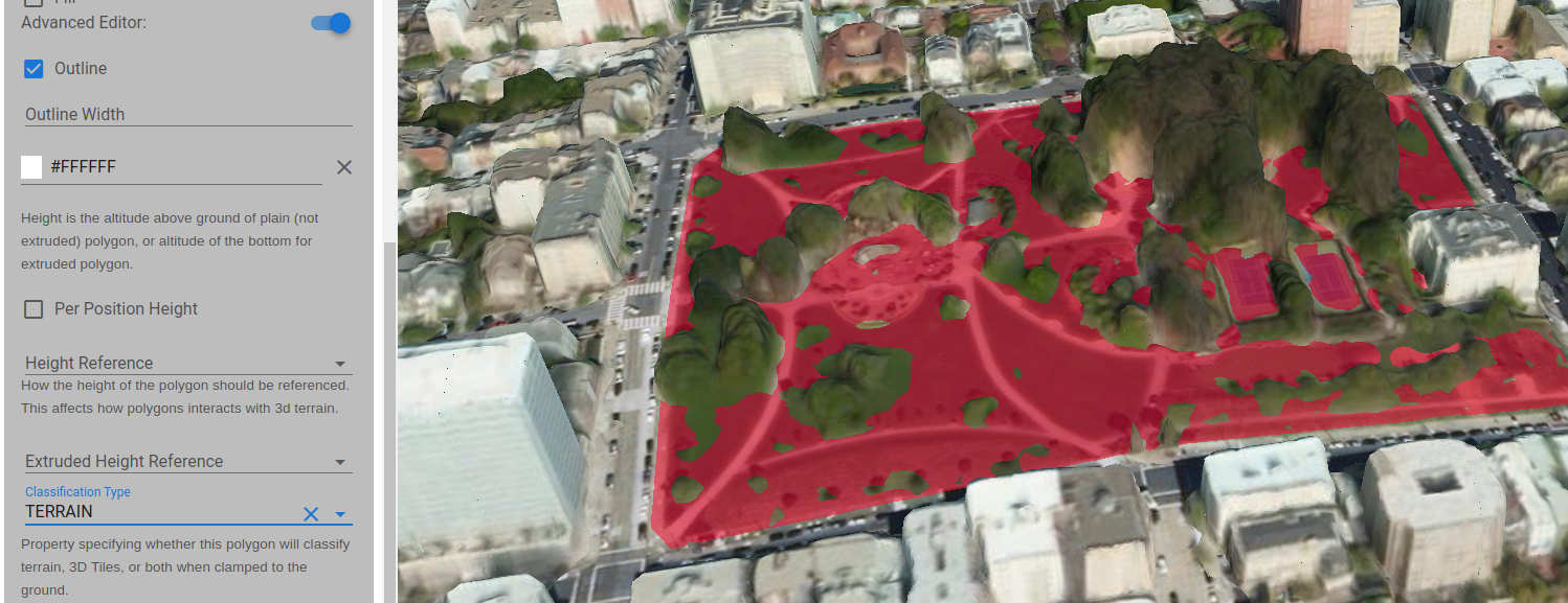
Next, let’s use the Classification Type field, setting it to “TERRAIN” to select what the clamped polygon applies to:
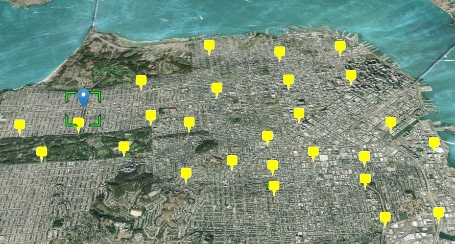
Now, let’s open some exported data. Here’s a typical set of exported points generated with geojson.io:
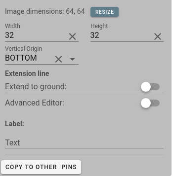
Let’s choose a point and change its icon and its icon’s vertical alignment (so it doesn’t fall through the terrain) and dimensions:
Here we have selected one icon and updated its properties to make it appear as we want, but changing all the icons one by one would take forever, especially for large data sets.
Click “COPY TO OTHER PINS”:
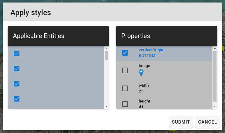
On the left is a list with all the entities to which the changed properties are applicable and on the right is the list of the properties that were changed for the model entity selected. By default, all the properties are checked to be copied to applicable entities but in this example we only want to change the vertical alignment for all the pins, but want to keep the icon and icon dimension of the other pins unchanged. So we uncheck the image, width and height properties:
Below we see how our scene looks after the update is applied. All the pins are above the ground, but the icons and dimensions are not changed:
After you have all the data styled the way you want, download your CZML!
The Cesium KML-CZML Editor code is Apache 2 licensed. It is available here.
cesium google-earth gis open-source visionport kml
Comments